
|
Input Configurations
|
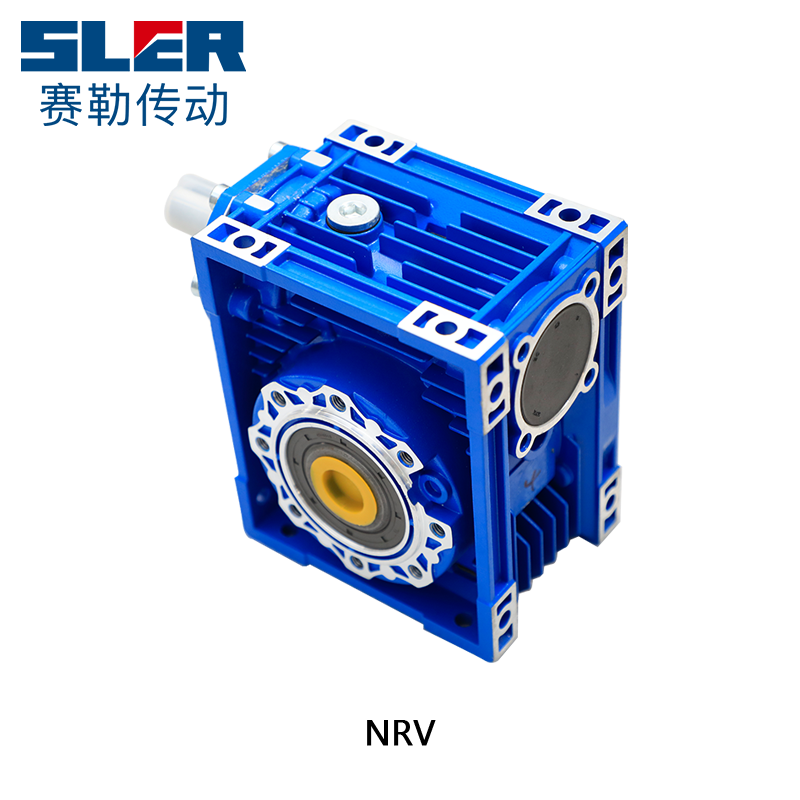
Double or single input shaft (NRV)
|
|
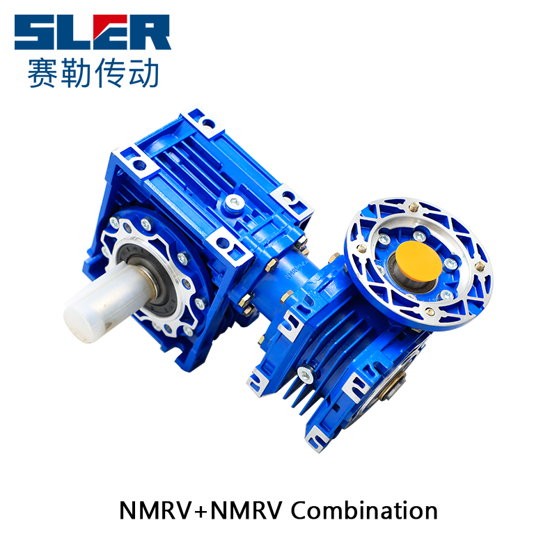
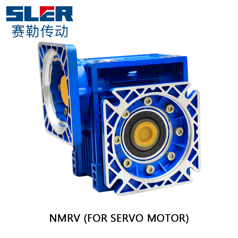
PAM / IEC motor input shaft with circle or square flange (NMRV)
|
|
|
Output Configurations
|
Double or single output shaft
|
|
Output flange
|
|
Model
|
Motor Input Flange (circle)
|
Transmission Ratio
|
Power
(kw)
|
Ratio
(i)
|
Nominal Torque
(Nm)
|
|||||||||||||||
|
PAM / IEC
|
Internal Dia.
|
Dis. Between Diagonal Screw Holes
|
External Dia.
|
Width of Key Slot
|
5
|
7.5
|
10
|
15
|
20
|
25
|
30
|
40
|
50
|
60
|
80
|
100
|
||||
|
N
|
M
|
P
|
E
|
Diamter of Input Shaft
|
||||||||||||||||
|
NMRV25
|
56B14
|
50
|
65
|
80
|
3
|
9
|
—
|
9
|
—
|
0.06
|
7.5-60
|
2.6-14
|
||||||||
|
NMRV30
|
63B5
|
95
|
115
|
140
|
4
|
11
|
—
|
0.06-0.18
|
7.5-80
|
2.6-14
|
||||||||||
|
63B14
|
60
|
75
|
90
|
|||||||||||||||||
|
56B5
|
80
|
100
|
120
|
3
|
9
|
—
|
||||||||||||||
|
56B14
|
50
|
65
|
80
|
|||||||||||||||||
|
NMRV40
|
71B5
|
110
|
130
|
160
|
5
|
14
|
—
|
0.09-0.37
|
7.5-100
|
11-53
|
||||||||||
|
71B14
|
70
|
85
|
105
|
|||||||||||||||||
|
63B5
|
95
|
115
|
140
|
4
|
11
|
|||||||||||||||
|
63B14
|
60
|
75
|
90
|
|||||||||||||||||
|
56B5
|
80
|
100
|
120
|
3
|
—
|
9
|
||||||||||||||
|
NMRV50
|
80B5
|
130
|
165
|
200
|
6
|
19
|
—
|
0.12-0.75
|
7.5-100
|
21-89
|
||||||||||
|
80B14
|
80
|
100
|
120
|
|||||||||||||||||
|
71B5
|
110
|
130
|
160
|
5
|
14
|
—
|
||||||||||||||
|
71B14
|
70
|
85
|
105
|
|||||||||||||||||
|
63B5
|
95
|
115
|
140
|
4
|
—
|
11
|
||||||||||||||
|
NMRV63
|
90B5
|
130
|
165
|
200
|
8
|
24
|
—
|
0.25-1.5
|
7.5-100
|
56-166
|
||||||||||
|
90B14
|
95
|
115
|
140
|
|||||||||||||||||
|
80B5
|
130
|
165
|
200
|
6
|
19
|
—
|
||||||||||||||
|
80B14
|
80
|
100
|
120
|
|||||||||||||||||
|
71B5
|
110
|
130
|
160
|
5
|
—
|
14
|
||||||||||||||
|
71B14
|
70
|
85
|
105
|
|||||||||||||||||
|
NMRV75
|
100/112B5
|
180
|
215
|
250
|
8
|
—
|
28
|
—
|
0.55-4
|
7.5-100
|
90-269
|
|||||||||
|
100/112B14
|
110
|
130
|
160
|
|||||||||||||||||
|
90B5
|
130
|
165
|
200
|
8
|
24
|
—
|
||||||||||||||
|
90B14
|
95
|
115
|
140
|
|||||||||||||||||
|
80B5
|
130
|
165
|
200
|
6
|
—
|
19
|
||||||||||||||
|
80B14
|
80
|
100
|
120
|
|||||||||||||||||
|
71B5
|
110
|
130
|
160
|
–
|
—
|
14
|
||||||||||||||
|
NMRV90
|
100/112B5
|
180
|
215
|
250
|
8
|
—
|
28
|
—
|
0.55-4
|
7.5-100
|
101-458
|
|||||||||
|
100/112B14
|
110
|
130
|
160
|
|||||||||||||||||
|
90B5
|
130
|
165
|
200
|
8
|
24
|
—
|
||||||||||||||
|
90B14
|
95
|
115
|
140
|
|||||||||||||||||
|
80B5
|
130
|
165
|
200
|
6
|
—
|
19
|
||||||||||||||
|
80B14
|
80
|
100
|
120
|
|||||||||||||||||
|
NMRV110
|
132B5
|
230
|
265
|
300
|
10
|
–
|
38
|
—
|
1.1-7.5
|
7.5-100
|
242-660
|
|||||||||
|
132B14
|
130
|
165
|
200
|
–
|
||||||||||||||||
|
100/112B5
|
180
|
215
|
250
|
8
|
28
|
—
|
||||||||||||||
|
90B5
|
130
|
165
|
200
|
—
|
24
|
|||||||||||||||
|
90B14
|
95
|
115
|
140
|
–
|
||||||||||||||||
|
80B5
|
130
|
165
|
200
|
—
|
19
|
|||||||||||||||
|
NMRV130
|
132B5
|
230
|
265
|
300
|
10
|
—
|
38
|
—
|
2.2-7.5
|
7.5-100
|
333-1596
|
|||||||||
|
132B14
|
130
|
165
|
200
|
–
|
||||||||||||||||
|
100/112B5
|
180
|
215
|
250
|
8
|
—
|
28
|
||||||||||||||
|
90B5
|
130
|
165
|
200
|
–
|
—
|
24
|
||||||||||||||
|
90B14
|
95
|
115
|
140
|
|||||||||||||||||
|
NMRV150
|
160B5
|
250
|
300
|
350
|
12
|
—
|
42
|
—
|
2.2-15
|
7.5-100
|
570-1760
|
|||||||||
|
132B5
|
230
|
265
|
300
|
10
|
—
|
38
|
—
|
|||||||||||||
|
132B14
|
130
|
165
|
200
|
–
|
||||||||||||||||
|
100/112B5
|
180
|
215
|
250
|
8
|
—
|
28
|
||||||||||||||
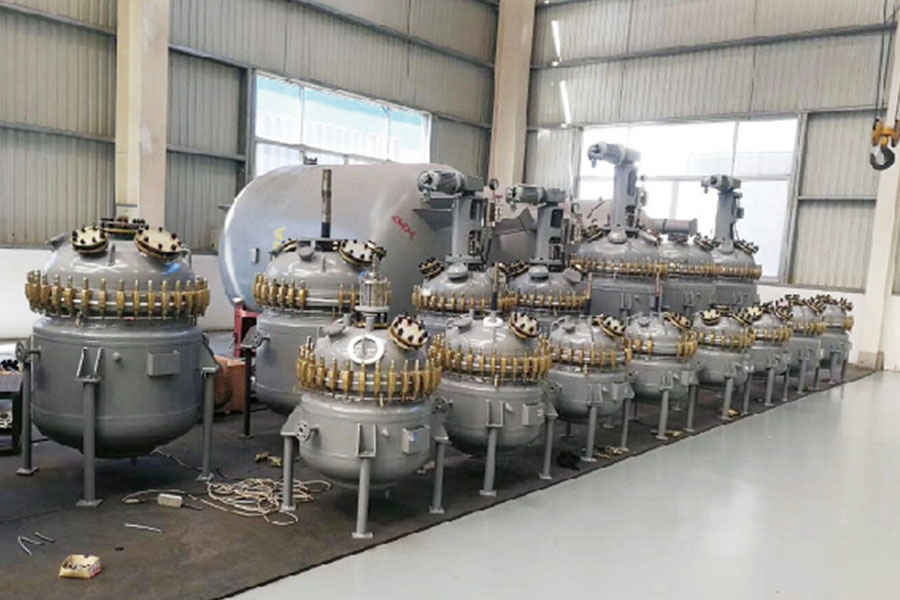
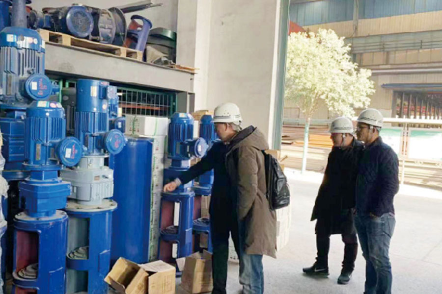
SLER has produced worm gear speed reducers and wholesale helical gear reducers configurations within its 10,000 sqm2 production facility in Hangzhou China.
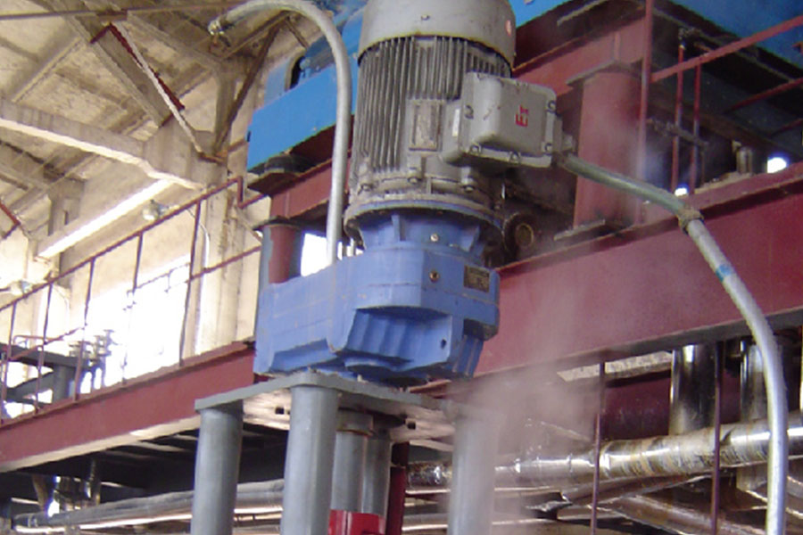
We offer our customers the best, reliable and flexible options and solutions for their application which includes food industry, cement factories, construction, logistics, mining, quarries, agriculture, as well as oil and gas.
Meanwhile, we are also a professional China worm gear speed reducer manufacturers and worm gear speed reducer suppliers.
Our drive is rooted in our passion for our products and the service that supports our customers.


Founded(year)

Registered capital (USD)

Daily output(pcs)

Annual sales(USD)


Helical bevel gear motors adopt a variety of strategies and technical means when balancing mechanical strength and lightweight requirements. Material selection: First of all, in terms of material sel...
Helical bevel gear motors are favored in the field of heavy-duty machinery, mainly because their unique design features and technical advantages can meet the high strength, high load and high reliabil...
In the face of fierce market competition, if helical bevel gear motors want to achieve differentiated competition, they can start from the following aspects: Technological innovation: Continuous inve...
The geometry and design of a helical gear reducer housing play a crucial role in determining its performance and heat dissipation capabilities. A well-designed housing facilitates efficient heat trans...
The selection of housing materials for helical gear reducers is a critical aspect of the design process, especially concerning thermal conductivity and heat dissipation properties. The choice of housi...
Helical gear reducers are designed to efficiently manage the heat generated during operation to ensure optimal performance and longevity. Heat management is crucial because excessive heat buildup can ...
The layout of Helical Worm Gear Motors offers wonderful blessings in diverse situations when compared to different gear configurations, inclusive of spur gears or planetary gears. Here's an exploratio...
The reduced noise level of Helical Bevel Gear Motors is particularly advantageous in various industrial applications where noise control is a critical consideration. Here's a detailed explanation of t...
Choosing materials for Helical Bevel Gear Motors that ensure compatibility with lubricants and prevent issues such as wear, friction, and overheating involves considering various factors related to th...
The adjustable nature of Helical Bevel Gear Motors plays a crucial role in optimizing directional adjustments in machinery layouts, offering a versatile solution to accommodate various spatial and ali...
The continuous tooth engagement in helical gear motors significantly impacts their ability to transmit torque efficiently. This feature is a key contributor to the high efficiency and smooth operation...
The standard performance of the Worm Gear Speed Reducer in a wind turbine software is inspired through numerous key factors that together determine the effectiveness of the machine: Gear Train Effici...
Address: Group 3, He'shun Village, Jing'jiang Street, Hangzhou City, China 311223
Copyright © SLER Transmission Devices (Hangzhou) Co., Ltd. All Rights Reserved.
 China Wholesale Worm Gear Speed Reducer Manufacturers

 English
 中文简体
中文简体 русский
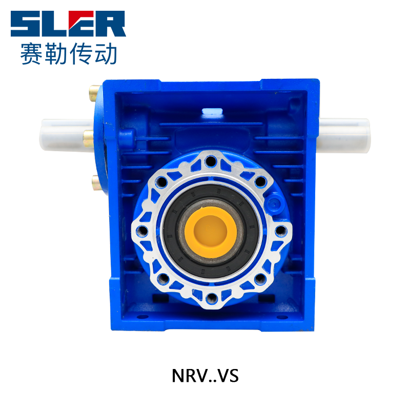
-1.png)
1.png "Helical Bevel Gear Motor (K Type)")
1.png "Helical Gear Motor (R Type)")
1.png "Helical Worm Gear Motor (S Type)")
a.png "Parallel Shaft Helical Gear Motor (F Type)")


